
Price: [price_with_discount]

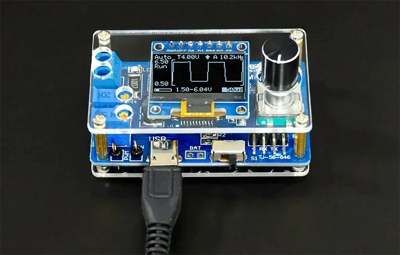
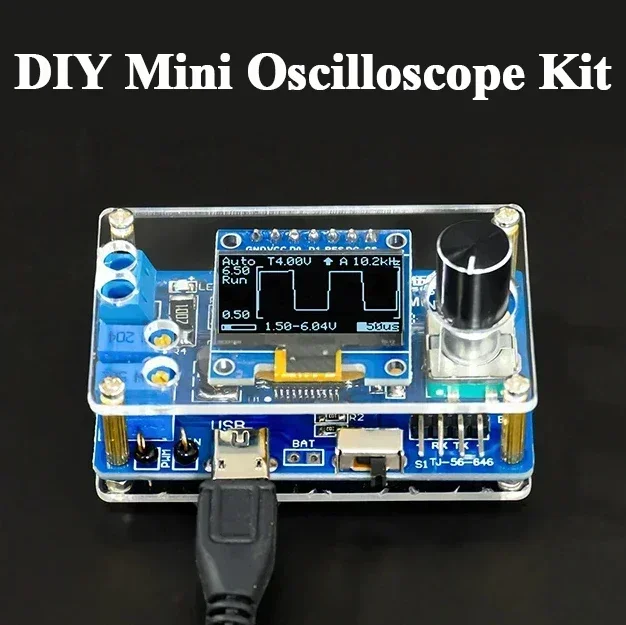
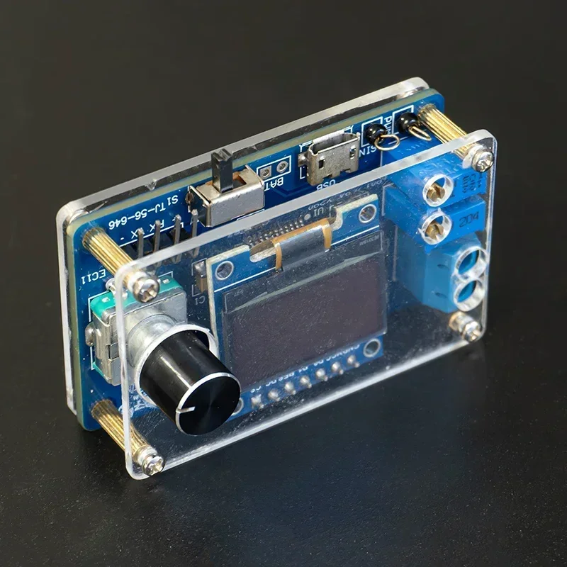
Product title: MiNi-DSO microcontroller oscilloscope package
Product mannequin: TJ-56-646
PCB dimension: 57 * 34mm
Working voltage: 4-5V
Single chip: STC8A8K64S4A12
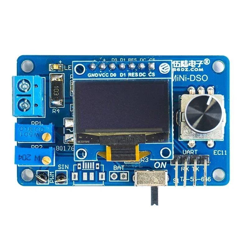
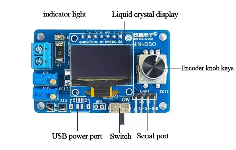
Display: 0.96 inch OLED show display -7P, 128 * 64 decision
Number of channels: single channel
Sec/div: 500ms, 200ms, 100ms, 50ms, 20ms, 10ms, 5ms, 2ms, 1ms, 500us, 200us, 100us (100us solely obtainable in computerized set off mode)
Voltage vary: 0-30V
Sampling degree: 10kHz@100us /Div
Trigger degree: Trigger voltage degree
Trigger slope: ↑ – rising edge, ↓ – falling edge set off
Trigger mode: A-automatic mode, N-normal mode, S-single mode.
Product introduction:
This is a straightforward oscilloscope made with an STC8A8K microcontroller. It solely requires a small quantity of parts and is simple to assemble. The perform can cowl easy measurements. This package goals to construct a primary oscilloscope mannequin with the only doable ideas and as little {hardware} as doable. The supply code is simple to grasp, and it is usually very appropriate for digital lovers to study and analysis whereas utilizing the product.

*Trigger degree: For repetitive indicators, the set off degree stabilises the show. For single-shot indicators, the set off degree captures it.
*Trigger Slope: The set off slope determines whether or not the set off level is on the rising or falling fringe of the sign.
*Trigger Mode:
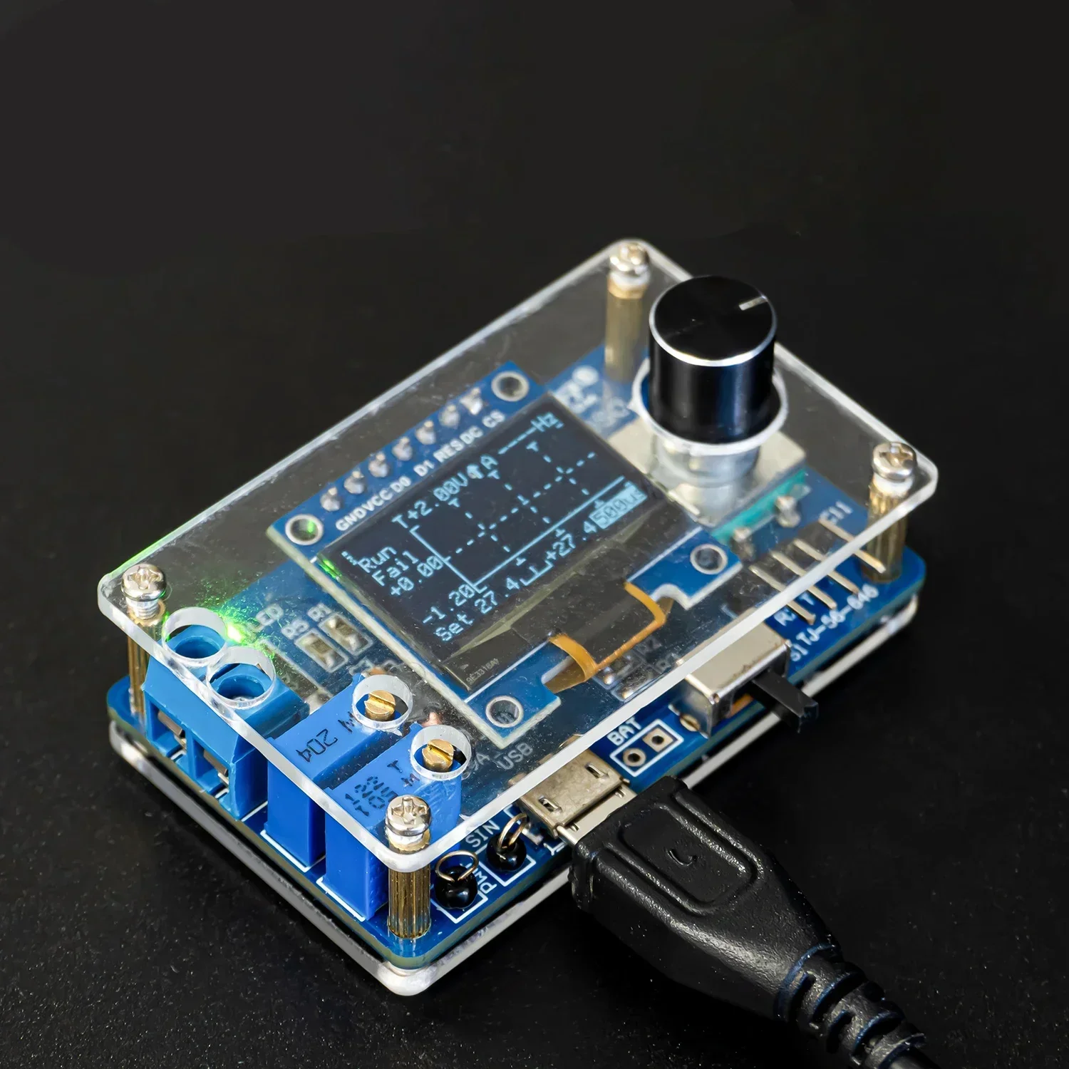
*Auto Mode: steady scanning. Click the encoder to cease or run sampling. If triggered, the waveform will probably be proven on the show and the set off place will probably be positioned within the centre of the graph. Otherwise, the waveform will scroll irregularly and show "Fail".
*Common Mode: After the pre-sampling is accomplished, you may enter the sign. If triggered, the waveform will probably be proven on the show, ready for a brand new set off. If there isn’t any new set off, the waveform will probably be saved.
*Single Mode: After the pre-sampling is accomplished, the sign could be enter. If triggered, the waveform is displayed and the sampling is stopped. User wants single level encoder to start out the following sampling.
*When in frequent mode and single mode, make sure that the set off degree has been adjusted accurately, in any other case the waveform won’t be proven on the show.
*Indicator mild: Normally the indicator mild is on to point that sampling is working.
*Save Setup: When exiting the setup interface, all parameters of the setup interface and major interface will probably be saved in EEPROM.
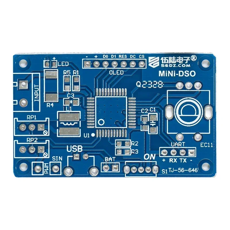
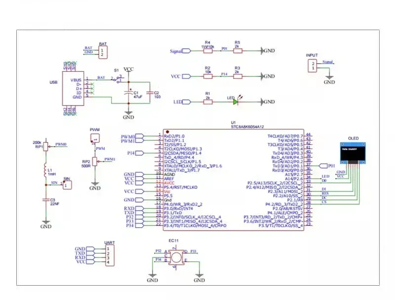
Circuit diagram:
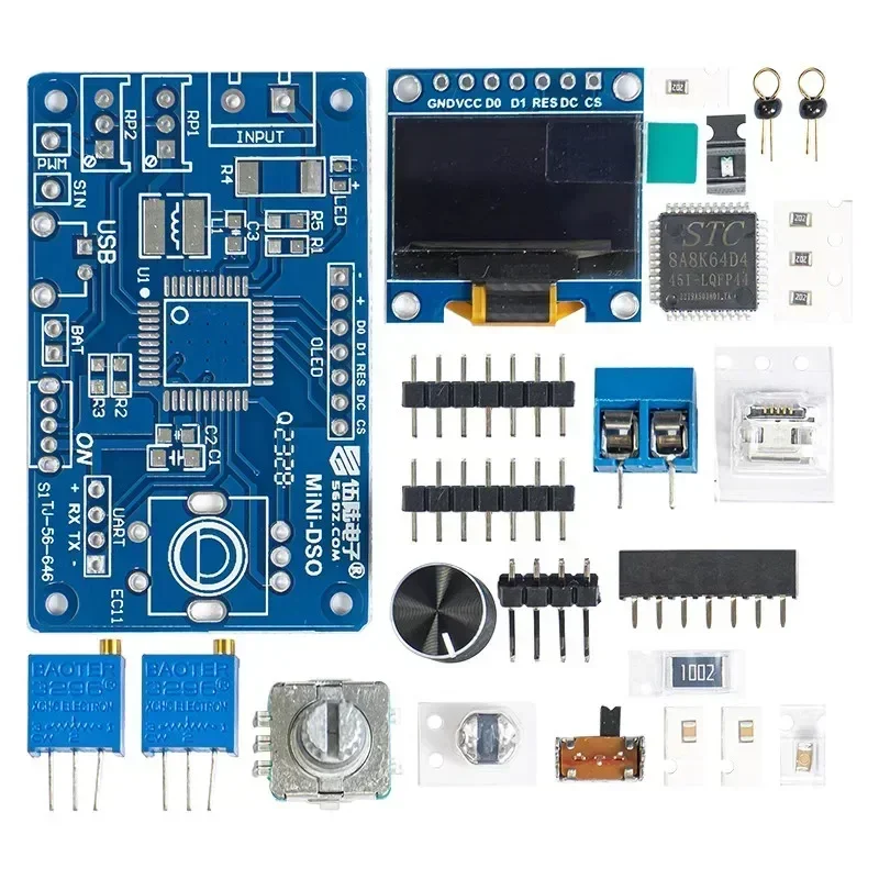
Package contains:
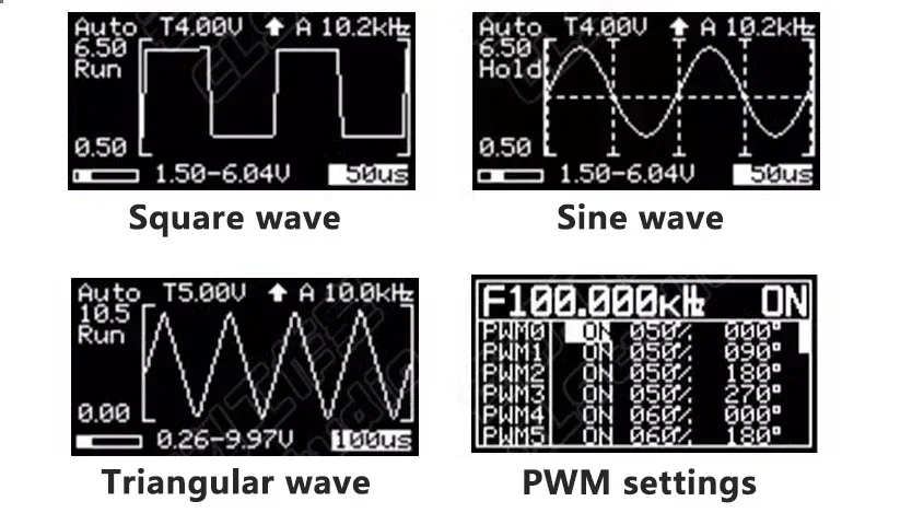
Function preview:
Product mannequin: TJ-56-646
PCB dimension: 57 * 34mm
Working voltage: 4-5V
Single chip: STC8A8K64S4A12
Display: 0.96 inch OLED show display -7P, 128 * 64 decision
Number of channels: single channel
Sec/div: 500ms, 200ms, 100ms, 50ms, 20ms, 10ms, 5ms, 2ms, 1ms, 500us, 200us, 100us (100us solely obtainable in computerized set off mode)
Voltage vary: 0-30V
Sampling degree: 10kHz@100us /Div
Trigger degree: Trigger voltage degree
Trigger slope: ↑ – rising edge, ↓ – falling edge set off
Trigger mode: A-automatic mode, N-normal mode, S-single mode.
Product introduction:
This is a straightforward oscilloscope made with an STC8A8K microcontroller. It solely requires a small quantity of parts and is simple to assemble. The perform can cowl easy measurements. This package goals to construct a primary oscilloscope mannequin with the only doable ideas and as little {hardware} as doable. The supply code is simple to grasp, and it is usually very appropriate for digital lovers to study and analysis whereas utilizing the product.
*Trigger degree: For repetitive indicators, the set off degree stabilises the show. For single-shot indicators, the set off degree captures it.
*Trigger Slope: The set off slope determines whether or not the set off level is on the rising or falling fringe of the sign.
*Trigger Mode:
*Auto Mode: steady scanning. Click the encoder to cease or run sampling. If triggered, the waveform will probably be proven on the show and the set off place will probably be positioned within the centre of the graph. Otherwise, the waveform will scroll irregularly and show "Fail".
*Common Mode: After the pre-sampling is accomplished, you may enter the sign. If triggered, the waveform will probably be proven on the show, ready for a brand new set off. If there isn’t any new set off, the waveform will probably be saved.
*Single Mode: After the pre-sampling is accomplished, the sign could be enter. If triggered, the waveform is displayed and the sampling is stopped. User wants single level encoder to start out the following sampling.
*When in frequent mode and single mode, make sure that the set off degree has been adjusted accurately, in any other case the waveform won’t be proven on the show.
*Indicator mild: Normally the indicator mild is on to point that sampling is working.
*Save Setup: When exiting the setup interface, all parameters of the setup interface and major interface will probably be saved in EEPROM.
Circuit diagram:
Package contains:
Function preview: